Operating Instructions
Follow following instructions while foundationing meehme and operating machine.
1) Use Anti Vibration mount of 100dia pad and 12mm dia bolt. Four holes are provided in base
plate and level the machine with the help of 4 holes on corner of the machine base with the
help of Quality level for 'X' and 'Y' axis on scraped slide.
2) Ensure that the lubricating cups and points are filled. Do not operate machine without
lubricating oil.
3) Fill Hydraulic power pack Tank with Hydraulic oil. Coolant tank capacity is 30 Liters.
4) Fill coolant tank with suitable soluble cutting oil. Coolant tank capacity is 30 Liters.
5) While supplying machine a self centering vice is located and fixed on cross slide. Exactly in to
centre. Reset the centre if by mistake the cross slides is disturbed.
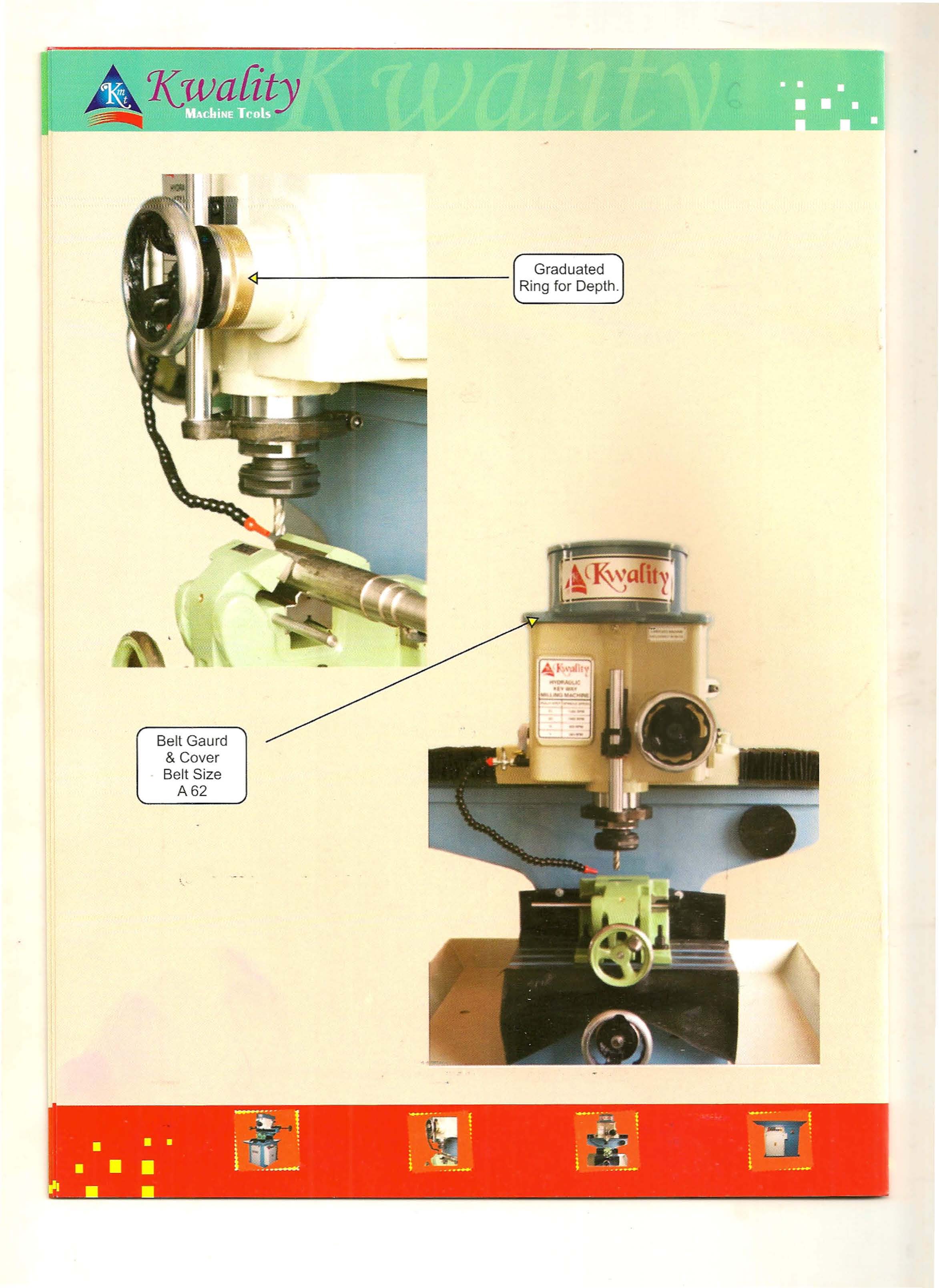
6) Feed control wheel is provided with dial ring having marking of per line of 0.063mm that is
complete round will have depth of 6.30mm. Depth setting drive rod is provided on left side of
control wheel to setthe depth with the help of slip gauge.
7) Use two flute cutters for best key way finishing with E40 collet without Tail.
8) Specifications of machine are as mentioned on last page.
9) Features of our machine are as follows.
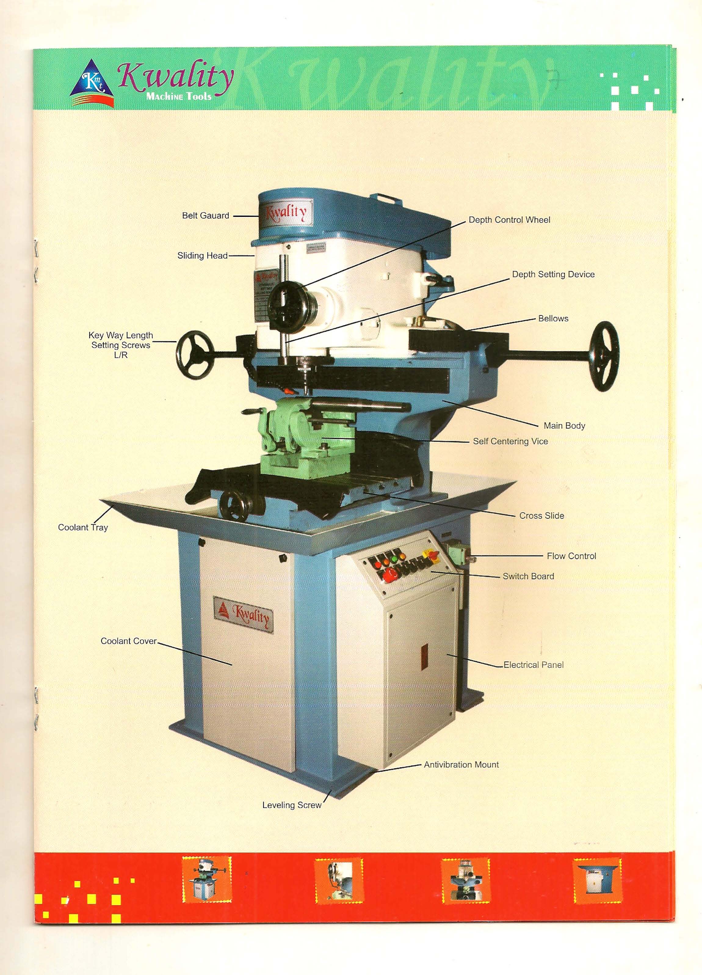
A) Body &Sliding Head
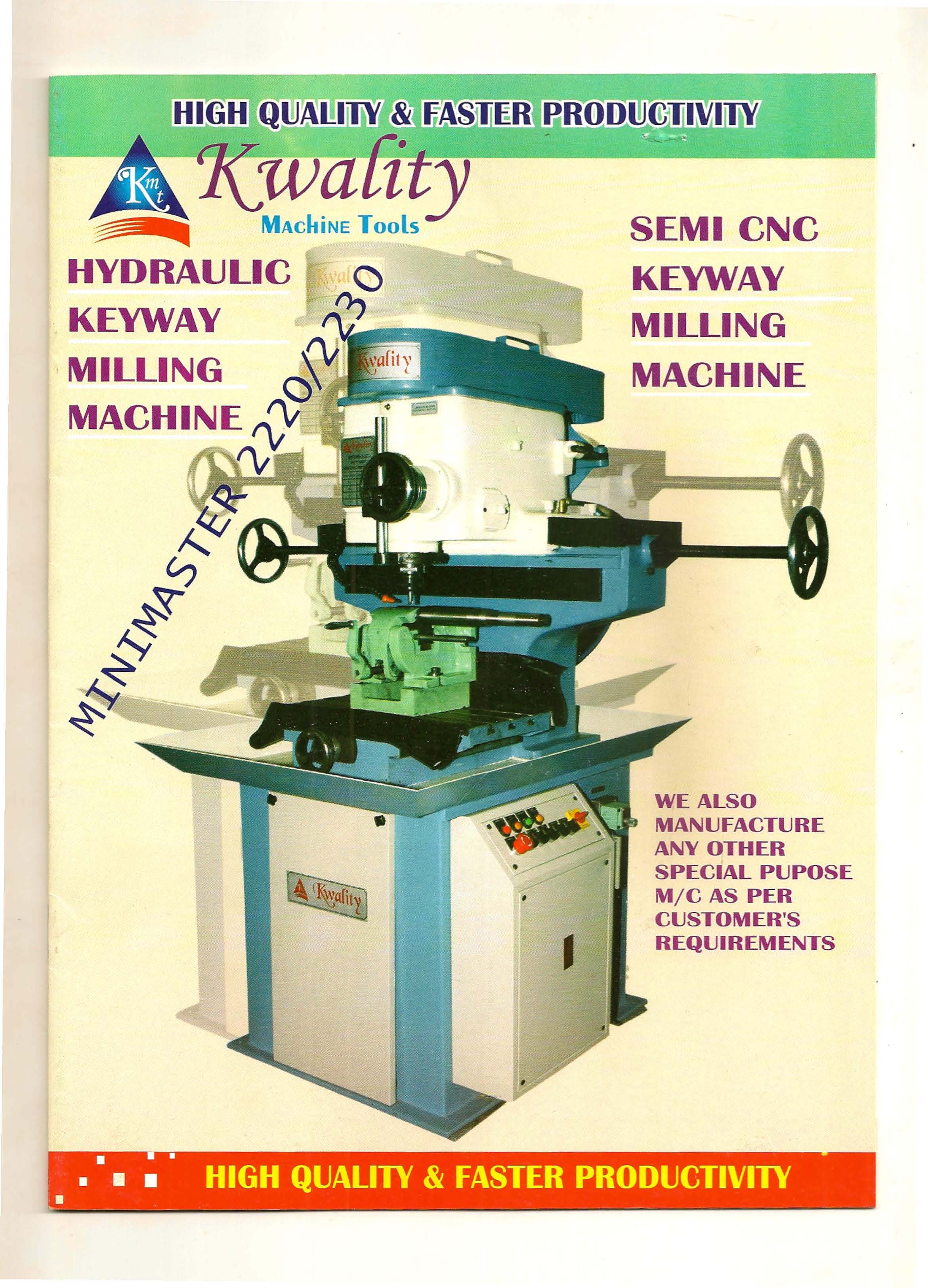
Manufacturing a machine of Excellence that allows complete value for money was a task.
We are at service to the costumer & user this 'Mini Master 2220 and 2230' made out of
close grain heavily ribbed cast iron casting to ensure vibration free operation.
B) Sliding Sleeve
Manufactured out of seamless Tube located and slides Vertically in sliding head into
closely Honed Bore.
C) Spindle
Mini Master 2220 & 2230 comes with a spindle for holding cutting tools. it has highly
durable and maintenance free features adding firmness originally and stiffness is the
two bottom and one top, single Row Ball bearings originated from FAG, Timken or SKF.
Noiseless spindle runs at accuracy within 5 microns.
D) Hydraulic Power Pack & Coolant Tank
Both these power pack and coolant tank are located in Bottom stand.
Power pack can generate 35kg.cm2 with help of 1HP motor, along with pump having
capacity of 4 LPM.
Our Machine
With the help of our machine customer can cut parallel key ways and as well as Wood Ruff Key
Way9!ecking sliding head and moving cross slide on request at additional cost.
We state following information as Example for time saving and profit making to the customer.
If a Key Way of 6mm wide X 3mm deep & of 2Smm length is to be done our machine requires
only 30 seconds to finish key way including loading & unloading time.
For larger diameters of shafts having a longer length we can design and supply our Hydraulic key
way milling machine as custom built machine.
We have our two models presently as mini master 2220 which can cut key ways from 2mm to
20mm width and second mini master 2230 which can cut key way from 2mm to 30mm width.
Both models can cut keys up to a length of 32Smm for larger Key Way length up to 600mm our
machine can be made available on request as modified version.
Operating Instructions
Following is the sequence of operation. Please follow carefully.
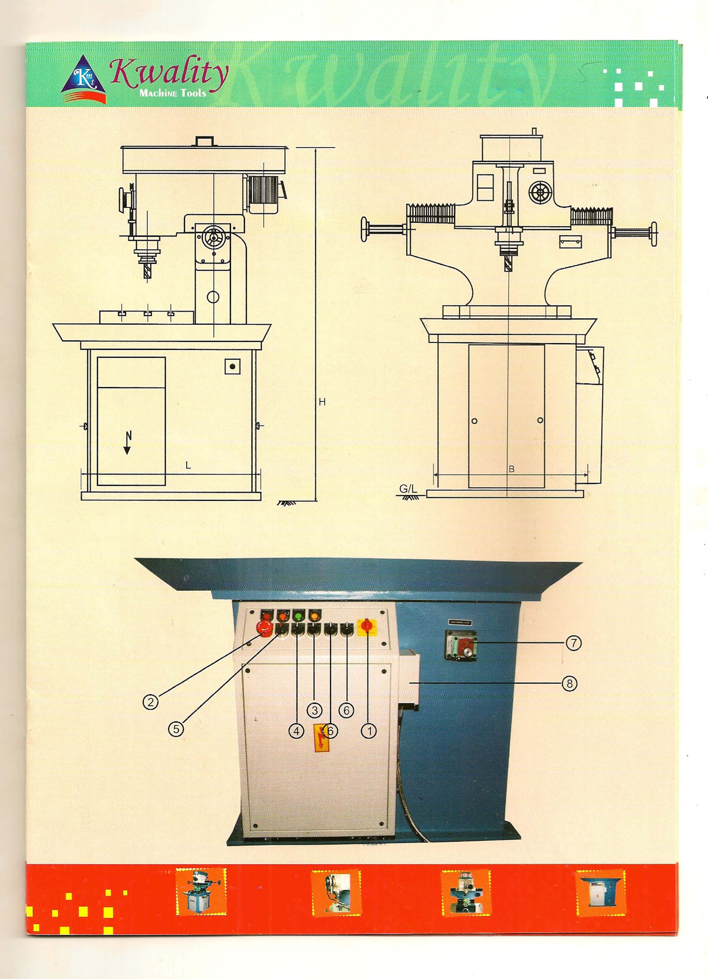
1) Operate main switch in on condition.
2) Release emergency switch.
3) Operate Hydraulic switch.
4) Operate L/Rswitch manually for setting.
S) Start Auto cycle for putting machine for production.
6) Startcoolant&spindlewhen required.
7) Red indicator will glow when required.
8) If red indicator blinks means emergency switch is pressed on or one of the overloads is
tripped Reset itto start machine.
9) Yellow indicator will glow when sliding head travels towards left side.
10) Same applies with right side.
11) When Green Indicator glow when pressure switch Operates. It should glow when slide is at
anyone of the slide end. if it glow in between travel turn pressure switch clock wise slightly.
If it does not glow even at the end turn pressure switch anti clock wise slightly. (This may
be required to do only if pressure switch disturbed)
12) For any problem in panel box it should be Opened by any person conversant with electrical
knowledge after main switch is in off condition of machine. Use Electrical Circuit diagram
to over come the problem.
SEMI CNC KEY WAY MILLING MACHINE
HIGH QUALITY &. FASTER PRODUCTIVITY
KWALITY ENGINEERING WORKS
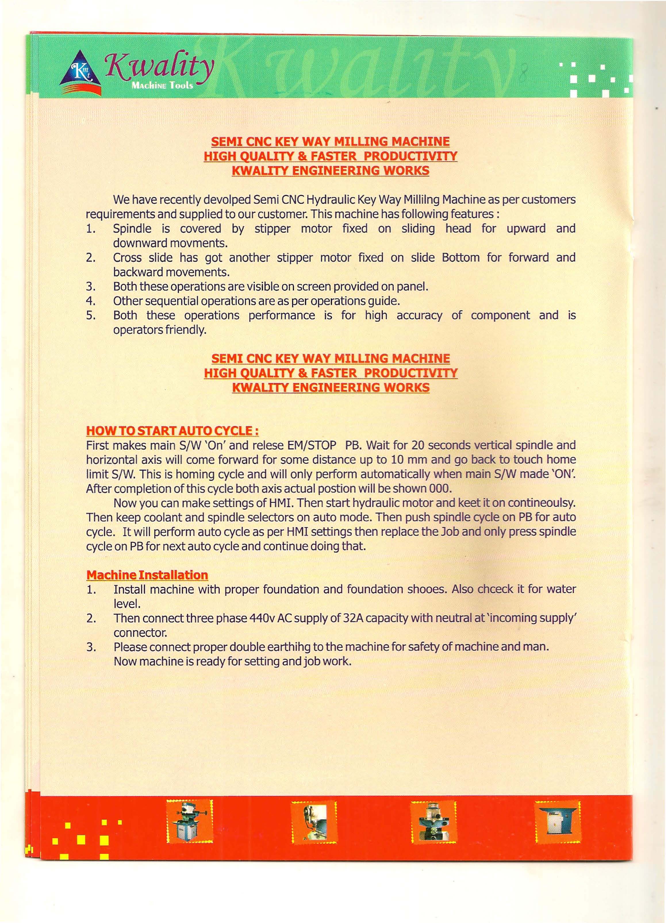
We have recently devolped Semi CNC Hydraulic Key Way Millilng Machine as per customers
requirements and supplied to our customer. This machine has following features:
1. Spindle is covered by stipper motor fixed on sliding head for upward and
downward movments.
2. Cross slide has got another stipper motor fixed on slide Bottom for forward and
backward movements.
3. Both these operations are visible on screen provided on panel.
4. Other sequential operations are as per operations guide.
5. Both these operations performance is for high accuracy of component and is
operators friendly.
HOW TO START AUTO CYCLE:
First makes main S/W 'On' and relese EM/STOP PB. Wait for 20 seconds vertical spindle and
horizontal axis will come forward for some distance up to 10 mm and go back to touch home
limit S/W. This is homing cycle and will only perform automatically when main S/W made 'ON',
After completion of this cycle both axis actual postion will be shown 000.
Now you can make settings of HMI. Then start hydraulic motor and keet it on contineoulsy.
Then keep coolant and spindle selectors on auto mode. Then push spindle cycle on PBfor auto
cycle. It will perform auto cycle as per HMI settings then replace the Job and only press spindle
cycle on PBfor next auto cycle and continue doing that.
Machine Installation
1. Install machine with proper foundation and foundation shooes. Also chceck it for water
level.
2. Then connect three phase 440v ACsupply of 32A capacity with neutral at 'incoming supply'
connector.
3. Please connect proper double earthihg to the machine for safety of machine and man.
Now machine is ready for setting and job work.
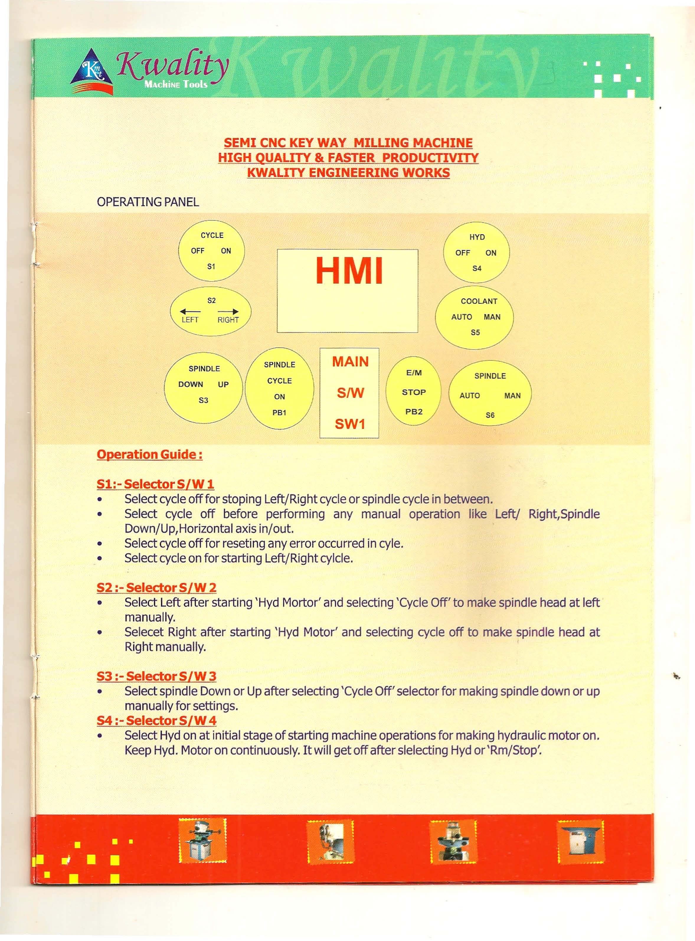
Operation Guide:
Sl:- Selector S/W 1
• Select cycle off for stoping Left/Right cycle or spindle cycle in between.
• Select cycle off before performing any manual operation like Left/ Right,Spindle
Down/Up,Horizontal axis in/out.
• Select cycle off for reseting any error occurred in cyle.
• Select cycle on for starting Left/Right cylcle.
S2:- Selector S/W 2
• Select Left after starting 'Hyd Mortor' and selecting 'Cycle Off' to make spindle head at left
manually.
• Selecet Right after starting 'Hyd Motor' and selecting cycle off to make spindle head at
Right manually.
S3 :- Selector S/W 3
• Select spindle Down or Up after selecting 'Cycle Off' selector for making spindle down or up
manually for settings.
S4:- Selector S/W 4
• Select Hyd on at initial stage of starting machine operations for making hydraulic motor on.
Keep Hyd. Motor on continuously. It will get off after slelecting Hyd or'Rrn/Stop.
S5:- SelectorS/W 5
Keep Selector on Auto mode for getting coolant motor On/Off as per auto cycle
requirement. In this mode coolant will be 'On' When spindle head earring down from home
limit S/W and get Off when spindle head reach to home limit S/W in spindle auto
cycle. coolant can be made 'On' Manually by selecting same selector coolant manually.
S6 :- Selector S/W 6
Same as per selector 5 but it is for spindle in place of coolant.
PBl :- Pushbutton 1.
Push this button to start spindle auto cycle. For performing this operation, first release
Em/Stop, then make Hyd motor on and make all settings in HMI. This PB will blink when
auto cycle is Off and remain 'On' continuously when auto cycle is 'On'.
PB2:- Pushbutton 2
Press this button for emergency stopping only. Also keep pressed when machine not in
use. Otherwise keep it released for all machine operations.
MainSwitch .
This will make machine three phase supply On/Off. Keep Off when machine not in use.
HMI Settings
HMI will glow when main S/W is made 'On'. Let it operate for 10-15 seconds after making
main S/W on. Then it will show settings and axis postions on different pages can be
scrowled through NEXT,BACKkeys. (Touch Screen) on bottom of HMI.
Page layout and setting limit are given in DVD along with the machine. Please refer it for
settings.
General description of HMI settings:
1. Counter - It will count No. of cycles completed by machine and can be reset to zero using
RESETkey.
2. Vertical axis autnal position - It will show actual postion of vertical axis from home limit
S/Wmm.
3. Horizantal axis actual Position - It will show actual postion of horizontal axis from home
limitS/W in mm.
4. Vertical axis Rapid distance - we can Set vertical axis rapid distance from home limit on in
this programme by touching on this valve.
5. vertical Axis cut distance per Step - we can set vertical axis cut distance per step in mm by
touching on this valve.
6. No. of steps - Set no. of steps to be taken of distance set in No.5 operation.
7. No. of Empty Steps - Set no. of empty steps to be taken for finishing of job as per
requirement.
8. Vertical axis rapid speed - speed of spindle coming down in rapid mode be set for general
purpose set is 1000 RPM.
9. Vertical axis cut speed - Speed of spindle coming down while cut step set it 100 for general
purpose.
10. Servo ACC- Set it 100 as default.
11. Servo DCC- Set it 100 as default.
12. Horizantal axis centre distance from Home - Set actual distance of centre of Vice/Job
from home limit S/W. once it is set will only require to change when you disturb vice
mounting.
13. Cutter Diameter - Set cutter Diameter in this valve. Check physical width sy test key way by
using cutter and set the same valve here. It will change as per cutter change or cutter
getting minousafter lot of use. This should not be bigger than keyway width.
14. Key Way Width - Set the key way width you want actually here. This should not be less
than cutter diameter otherewise HMI will not accept it. Set this valve before setting cutter
diameter for convenient operation.
15. Horizantal axis rapid speed - Set speed of horizontal axis you want. Generally keep it 1000 rpm.
16. Servo ACC- Set itlOO as default.
17. Servo DCC - Set it 100 as default.
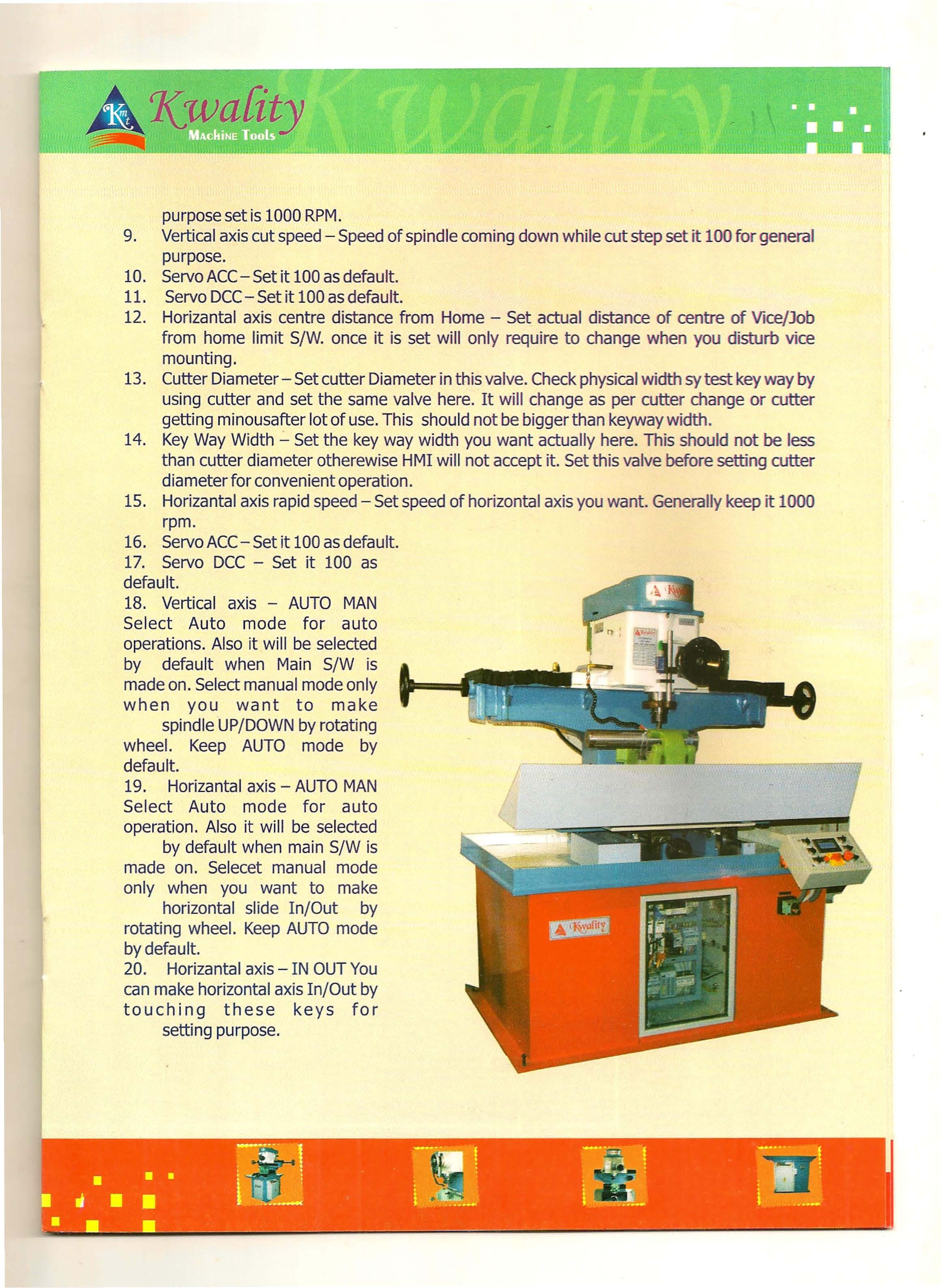
18. Vertical axis - AUTO MAN Select Auto mode for auto operations. Also it will be selected
by default when Main S/W is made on. Select manual mode only when you want to make
spindle UP/DOWN by rotating wheel. Keep AUTO mode by default.
19. Horizantal axis - AUTO MAN Select Auto mode for auto operation. Also it will be selected
by default when main S/W is made on. Selecet manual mode only when you want to make
horizontal slide In/Out by rotating wheel. Keep AUTO mode by default.
20. Horizantal axis - IN OUT You can make horizontal axis In/Out by touching these keys for
setting purpose.
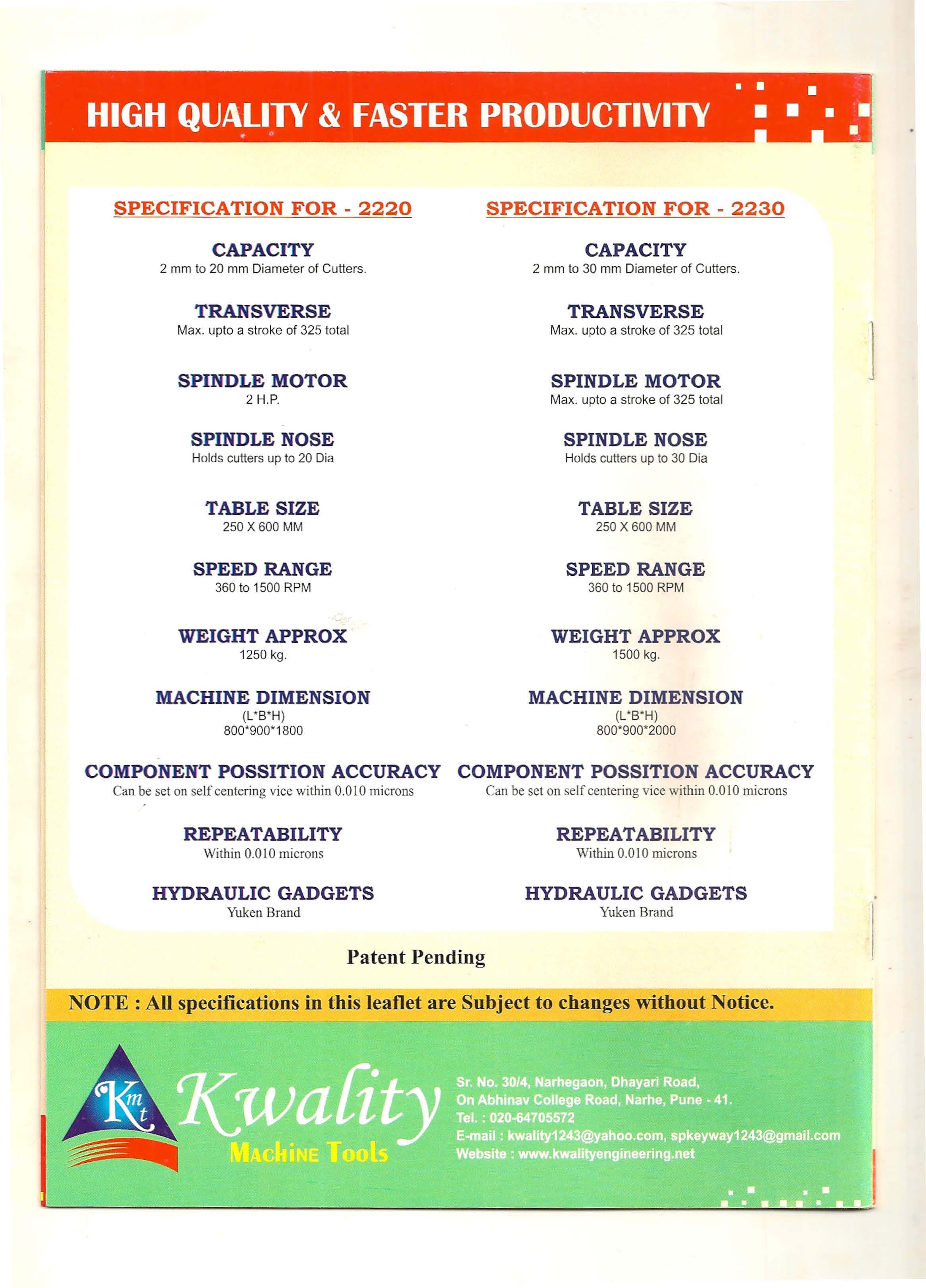
| SPECIFICATION FOR - 2220 |
SPECIFICATION FOR - 2230 |
CAPACITY
2 mm to 20 mm Diameter of Cutters. |
CAPACITY
2 mm to 30 mm Diameter of Cutters. |
TRANSVERSE
Max. upto a stroke of 325 total |
TRANSVERSE
Max. upto a stroke of 325 total |
SPINDLE MOTOR
2 H.P. |
SPINDLE MOTOR
Max. upto a stroke of 325 total |
SPINDLE NOSE
Holds cutters up to 20 Dia |
SPINDLE NOSE
Holds cutters up to 30 Dia |
TABLE SIZE
250 X 600 MM |
TABLE SIZE
250 X 600 MM |
SPEED RANGE
360 to 1500 RPM |
SPEED RANGE
360 to 1500 RPM |
WEIGHT APPROX
1250 kg. |
WEIGHT APPROX
1500 kg. |
MACHINE DIMENSION
(L *B*H) 800*900*1800 |
MACHINE DIMENSION
(L*B*H) 800*900*2000 |
|
COMPONENT POSSITION ACCURACY
Can be set on self centering vice within 0.0 I0 microns
|
COMPONENT POSSITION ACCURACY
Can be set on self centering vice within 0.0 I0 microns |
REPEATABILITY
Within 0.010 microns |
REPEATABILITY
Within 0.0 I0 microns |
HYDRAULIC GADGETS
Yuken Brand |
HYDRAULIC GADGETS
Yuken Brand |
Patent Pending
NOTE: All specifications in this leaflet are Subject to changes without Notice.

;)