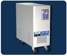
System Working Description
At morning when sun rays falls on solar PV Panels, it starts generating voltage. This voltage without load called OCV (Open Circuit Voltage) is measured by the micro controller. As soon as it is stable above 17V X No of panels connected in series for 20 seconds, the load is disconnected from grid by static switch. At the same time inverter is enabled in phase synchronize with grid and the load is powered by inverter. The solar panel total wattage is (normally) greater than the load power.
Now the inverter is powered by solar PV Cells through the charge controller. At the same time batteries ate charged. If some clouds are in the sky, the amount of energy generated from solar panel reduces. In such situation some part of energy is taken from batteries, but we want to use energy stored in batteries at power failure at night. As soon as half the batteries are discharged, the inverter stops and output load is power by grid power.
Now the batteries are charged partly by grid power and partly by solar power. As soon as batteries are charged to 13.5V x N the inverters starts and feds the load. At evening when solar voltage drops to 12V which is of no use the inverter is disabled and load is powered by grid power by static switch.
The charge controller maintains constant voltage across the batteries even though the input to charge controller is varing voltage obtained from the solar panels.
If the solar voltage is strong & the load connected to the output of inverter is low, then the excess power may charge the batteries at higher charging rate. This may cause heating the batteries, so life of batteries will reduce. This situation is overcome by limiting the current to the batteries.
In this way the priority of energy source to the load is achieved as follows:-
1st -- Solar
2nd -- Battery ( Half capacity)
3rd -- Grid
4th -- Battery (Remaining Half)
IDEAL FOR
Bunglows, hotels, Hospitals, Mobile Towers, Petrol Pumps, Schools, Resort, Banks, ATM's, Offices, Agriculture
TECHNICAL SPECIFICATION
|
Models
|
|
2 KVA
|
3 KVA
|
4 KVA
|
5 KVA
|
6 KVA
|
8 KVA
|
|
|
|
|
|
Battery Voltage
|
|
48V
|
72V
|
96V
|
120V
|
144V
|
180V
|
|
|
Input AC
|
165 V -- 275 V
|
|
Transfer Device
|
Static Switch made of Two Thyristors connected back to back
|
|
Waveform
|
Pure Sine Wave
|
|
Indications
|
Visual: Mains on, Inverter on,Overload, Battery Low, Charging On, System On, Solor on
Audio: Mains to Inverter at start Battery low early warning and overload
|
|
|
Input - Fuses & MCB
Over / Under Voltage cut-off
Battery Reverse - Fuse Link
Output - Electronic Trip for overload
|
|
Inverter
|
Full Bridge IGBT high frequency PWM
|
|
Display
|
7 Segment Display for Input A/C, Output A/C, Battery Voltage, Solar Voltage, Solar Current, Solar Power, Output current and battery current
|

